Royal Observer Corps Post Equipment
The future rôle of the Royal
Observer Corps, which is part of the United Kingdom Warning and
Monitoring Organisation, will be, as at present, to report nuclear
bursts and radioactive fallout.
Secretary of State for the Home Department, Hansard, 1 May 1968
ROC posts were provided with a range of equipment to fulfill a wide range of requirements, first there was the need for personnel to live below ground for a period immediately following a nuclear attack, this was estimated to be between two and three weeks. Sanitation was provided by an Elsan chemical toilet housed in the lower part of the entrance shaft. For sleeping a two tier bunk was located at the further end from the entrance. Cooking was done on a small solid fuel burner, and had to be done outside of the post, food was standard military survival rations. Water was stored in jerrycans. As far as comfort was concerned that was about it, other than some folding chairs. A small kit of tools was also provided to perform key functions such as mounting monitoring equipment, maintaining the generator and digging holes.
There was also the need for performing the primary function of the post, that is monitoring explosions and tracking radiation. The information gathered had to be communicated to the outside world, and so all posts had dedicated line communications, and one in every small cluster of 2-4 posts had a vhf radio transceiver, such posts were defined as master posts.
Some posts had an additional
responsibility of reporting basic meteorological information, for
this purpose they had a few extra devices, including a barometer for
measuring air pressure, an anemometer for measuring wind-speed and a
psychrometer for measuring temperature and relative humidity.
RADIAC equipment
All posts were equipped with RADIAC equipment, this is described on the Radiac Equipment page. Initially this comprised personal dosimeters together with a charger, a Meter Survey Radiac No 2 and a Fixed Survey meter or FSM. In the mid 1960s the Meter Survey Radiac was replaced with the lightweight survey meter. In 1982/83 this was again replaced, this time with the PDRM82. The FSM was replaced with the PDRM82F at about the same time, although training materials still referred to this as the FSM.
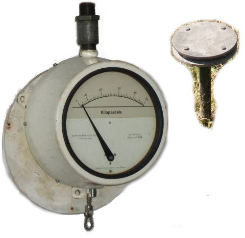
Bomb Power Indicator
Provided that the distance from ground zero is known, the power of a nuclear weapon can be calculated from the peak-overpressure produced by the blast wave. The Bomb Power Indicator (BPI) was designed to record this pressure.
The BPI comprises a metal bellows, rather like an aneroid barometer, one side of which is exposed to atmospheric pressure. Attached to the bellows is a push rod which bears against a lever fixed to a spindle. A pointer attached to the spindle moves across a scale reading from 0 to 50 kilopascals (kPa). Originally instruments were calibrated from 0 to 5 pounds per square inch (psi). Above ground a pair of circular baffle plates, six inches in diameter and separated by 1/2", protect the opening of the pipe which is connected to the gauge below ground in the protected monitoring post. The baffles were normally stored below ground and only screwed onto the top of the pipe at the start of exercises or at Transition To War. Outside of operations the BPI pipe was protected by a screw on cap and there was a drain valve at the base of the instrument to remove any excess rainwater.
If the BPI registered a reading of 0.3 p.s.i. or 2kPa, or higher, the operator would wait ten seconds before pressing the reset button and recording the reading prior to making an immediate report to the group control, in the form "Tocsin - Horsham 10 post - oh nine thirty five - pressure three point four, over." One minute after a BPI reading an observer would be sent above ground to change the photographic papers in the Ground Zero Indicator.
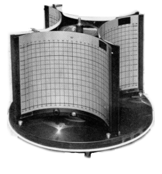
Ground Zero Indicator (GZI)
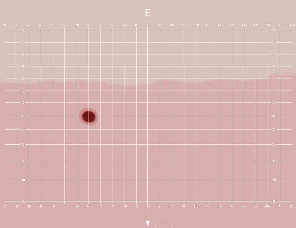
The GZI consisted of four horizontally mounted pinhole cameras each facing a cardinal compass point within a white enameled metal drum, each 'camera' contained a sheet of photosensitive paper mounted within a clear plastic cassette. The cassettes were positioned such that each pointed to a cardinal compass point, with a small overlap between each field of view. The cassette graticule was marked in five degree intervals in both elevation and azimuth. The vertical or elevation markings were from 15° below the horizon to 45° above. Each graticule was also marked with the cardinal compass point (N,E,S,W) against the central line running down the cassette. The limits of azimuth (bearing) were: N (North) 305° to 55°; E (East) 35° to 145°; S South) 125° to 235° and W (West) 215° to 325°.
The bright flash from a nuclear explosion would produce a mark on one or two of the papers within the drum. The position of the spot enabled the bearing and elevation of the burst to be estimated. The size of the spot would also give assistance in gauging the size of the explosion. With triangulation between neighbouring posts these readings would give an accurate altitude and position.
The altitude of the explosion was important because a ground or near ground burst would produce high levels of radioactive fallout, whereas an air burst would produce large distance and short lived initial radiations but relatively little fallout. Once combined with the peak-overpressure readings from post Bomb Power Indicator readings the power of the burst in megatons could also be calculated by the Triangulation Team in the group control building, using a hand held plastic calculator device.
When not in use the GZI was stored below ground. Upon manning up the post, the GZI was mounted on a domed plate affixed to the top of the access shaft. Three nuts were used, and the studs in the base of the GZI and the matching holes in the base were spaced in such a way that the instrument could only be fitted in one orientation. The orientation was determined during the installation of the mounting.
The post toolkit included a spanner for fitting the GZI to the mount, the opposite end of the spanner was of a larger size and became obsolete by the time the GZI was brought into general use, that end was for removing the cover. The later GZI had a hand operated release.
Changing GZI Papers
GZI papers were changed according to a routin based upon the time of year. In summer (21st March - 21st September) papers were changed twice a day, at noon and just after sunset. In winter on odd numbered dates only, just after sunset.
At posts the instruction to change papers, given by the No 1 observer, whether in response to a nuclear burst or otherwise, meant that the No 3 observer left the post, carrying the new papers in a light-proof satchel. No 3 would remove the top of the GZI, remove the cassettes and place them in the satchel. They would then insert the new cassettes in sequence and replace the lid.
The observer next returned to the observation room, if fallout had already arrived then they needed to decontaminate, but not before passing the exposed cassettes to the observer who assessed the papers. Assessment is too complex to go into here, but broadly the azimuth and elevation of the centre of any spots, whether or not a spot touches the horizon and the spot size were all determined prior to sending the report, this is given in the form below, in the case of a spot touching the horizon line, or if the horizon line is not visible, the 0° elevation line, then the word "clear" would be replaced by "touching".
The report to Group, of the GZI paper shown would be in the form: "Nuclear burst, Horsham ten post over." - Plotter responds, "Horsham ten post over." Horsham 10 post then reports, "Twelve sixteen - bearing zero six five - elevation two one - clear - spot size zero seven - over." Plotter responds; "Thank you, out."The Bomb Power Indicator and Ground Zero Indicator
Communications
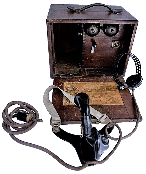
Telephone Observer AD 163b
Until the early 1960s, in its nuclear reporting role, the ROC used the AD 163b headset telephone to give voice communication with ROC Group HQ over a private telephone circuit shared with other members of a cluster. The AD 163b used magneto ringing and a battery for the speech circuit. This instrument had been in use during World War II.Tele Talk Unit AD 3460
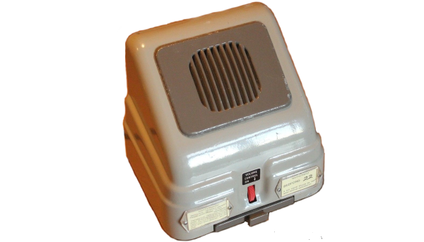
In the early 1960s the AD 163 was
replaced with the Tele Talk Unit AD 3460 - more correctly known as
Units Intercom LB AD 3460. This used two batteries, 67.5 volts for
the calling or signalling circuit, and 6 volts for speech. The
loudspeaker also functioned as the microphone. The volume control on
the left also switched the unit on and off. The lever switch on the
right was biased to the centre receive position. In the upwards
direction the switch sent the call signal. Depressing the switch
gave a press-to-talk (prestel) function. The telephone circuit was
shared with the WB400A warning receiver, this necessitated the
inclusion of a filter to remove the 72kHz carrier frequency from the
latter's signal.
Normally in receive mode any conversation on the cluster's shared line might be heard. Posts within a cluster could communicate among themselves by voice calling. But to attract the attention of the plotter in Group HQ, the lever switch was pushed upwards
The
pair of wires feeding them were often carried on poles along field
boundaries making them very vulnerable to blast damage. The same wires
fed both the Warning Receiver and the TeleTalk, so both would be out
of action if the line was broken. In the film Hole
in the Ground, the featured post sent an observer out in the
fallout to clear the line faults caused by the bomb exploding. This
was not an easy task in peacetime yet alone a post nuclear holocaust.
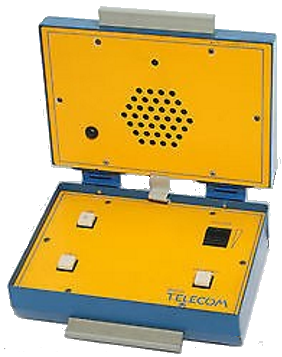
Loudspeaker Telephone AD8010
The Loudspeaker Telephone AD8010 aka "Teletalk" was introduced into posts in about 1982. This model was line powered and therefore required no batteries or mains power connections. All that was required was therefore a standard telephone line accessing into the monitoring post. It was of clam-shell design in bright blue and yellow. On the control panel were an ON/OFF lamp, a call button, transmit button and a volume control. The Unit was switched on simply by opening the lid. The ON/OFF lamp flashed regularly when connected to the line. To call Control the call button was pressed for at least five seconds and then released. To speak to control the Transmit button had to be pressed and held down as long as speaking, and released to listen. The volume control affected the loudspeaker only. Both the microphone and loudspeaker were in the lid.. To speak to other posts within the cluster it was onlly necessary to hold down the transmit switch without using the Call button.
On "manning up" the operation of the Teletalk had to be verified. The first task was to ensure that the links/plugs in the BT Case 200 or BT Testing Unity were in the "NORMAL" position, they may have been left in the "TEST" position by a BT engineer. The unit was switched on and a call made to control to verify correct operation.
At all times during operations and
exercises the Teletalk was to be manned continuously.
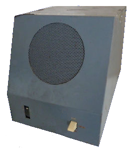
Carrier receivers
Operationally during the Cold War the
Director UKWMO would have been located at the United Kingdom
Regional Air Operations Command (UK RAOC) within Strike Command's
Operations Centre nuclear bunker at RAF High Wycombe to instigate
the national air raid warnings, with the Deputy Director located at
a standby UK RAOC, at Goosnargh near Preston within the UKWMO
Western Sector nuclear bunker. Warnings were instantly distributed
around the country by the HANDEL Warning Broadcast System via 250
Carrier Control Points located at major police headquarters thence
to over 1700 Carrier Receivers, initially the WB400A, but later the
WB1400, located in selected buildings such as schools, hospitals,
police stations, public houses, even occasionally a private house
and also at ROC posts. The WB400A was introduced in 1964/65, with
20,000 receivers installed.
WB400A Carrier Receiver
The WB400 receiver was powered by a six volt battery which could provide power for up to a year. Spare batteries were provided and it was expected the user would change them when necessary by removing the base-plate.
The red knob on the front was a combined On/Off and Volume control. Below that is a small pull out draw containing an instruction card telling the user what to do in response to a message and how to change the battery.
Upon
manning up the receiver was to be tested as follows, and the status
reported to control. The receiver was to be switched on and the volume
adjusted, correctly adjusted the receiver would emit a quiet tick like
a clock, of the monitor tone sent by the Carrier Control Point. The
audio volume increased automatically when a calling signal or voice
message was received.
WB1400 system
The WB400 system was phased out in the
early 80s, and replaced with the WB1400. It used the same 72kHz
carrier frequency, but every component of the Handel system was
replaced with more modern designs. At post level the equipment was
fitted to a wall-mounted BT communications board. Although these
were of a standard size, the actually wiring and some other
minor details varied, it is said that this depended on what the
engineer had in his van at the time. This board held the WB1401
Carrier Receiver and associated equipment.
The BT telephone line was connected at
the Block Terminal BT 52A, this was in turn connected to the Filter
Unit WB1401, from there to the Receiver Speech WB1401, and
finally to the Loudspeaker Unit WB1401. In the case of installations
in public places and offices, a desk-mounted speaker unit was used.
The WB1400 Carrier Receiver was in a waterproof, grey, diecast box
and contained the receiver complete with its battery. The battery
was a rechargeable 1Ah Nickel Cadmium type, trickle charged from the
exchange supply.
The Carrier Receiver fed the
Loudspeaker Unit WB1400. This had two controls, a combined ON/OFF
volume switch, and a test button. Upon manning up the procedure was
essentially the same as for the WB400. The unit was switched on, and
the test button depressed when the confidence tick would be heard.
Still holding down the button the volume could then be set. Tests
were to be carried out every hour during exercises and operations.
More
details of the Handel Systems can be found at http://www.ringbell.co.uk/ukwmo/index.htm
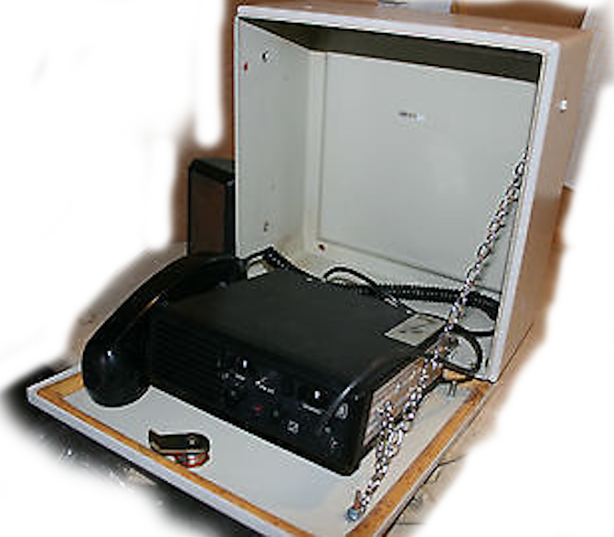
BE525 Post Radio
Typically one in three posts was a Master Post. Master Posts were equipped with VHF transceivers. Initially these were ATE Countryman single channel VHF radios. These early valve sets were not successful, and were replaced in the mid 1980s by fully transistorised sets operating in the frequency band 80.000-81.500 MHz. They were three channel FM sets built by Burndept, model No BE525. The antenna was external and fitted to a pneumatic mast.Local Warning
A significant part of the role of the Post crew, was giving the public warning of attack and fallout. Two methods were used, a hand-operated siren, the other being a 3-shot electrically fired maroon. Two types of siren were issued, they look very similar, the stands are the simple way of telling them apart, the Carter siren had an angle iron frame, whereas the Secomac had a tubular steel one.Power Generators
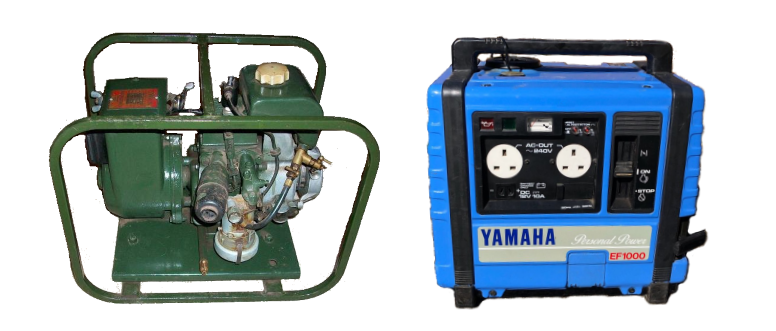
Posts had to be self-sufficient as far as power was concerned, they were equipped with a pair of re-chargeable 12 volt nickel iron (NiFe) batteries, these were later replaced with lead-acid batteries, and a petrol generator for charging them. The generator had to be operated on the surface for obvious reasons, and fuel was kept in a jerrycan buried in the ground. The original generators were made either by Swann, or A.C. Morrison. Later some posts were supplied with Yamaha 1000 generators which were also able to supply 240 volts ac. The power system covered lighting and the post radio if fitted. A switch was provided for switching between batteries, and a timer to disconnect the batteries automatically if the crew forgot to switch off when vacating the post.