RADIAC Equipment
Like taxes, radioactivity has long been with us and in increasing amounts; it is not to be hated and feared, but accepted and controlled. Radiation is dangerous, let there be no mistake about that—but the modern world abounds in dangerous substances and situations too numerous to mention. ... Consider radiation as something to be treated with respect, avoided when practicable, and accepted when inevitable.
- Ralph Eugene Lapp
RADIAC stands for RAdiation Detection, Indication And Computation. All parts of the UK civil defence services, during the Cold War, were required to be able to measure and interpret radiation measurements. As their roles differed somewhat the equipment they used varied a little, and also changed during the Cold War period. A variety of scientific units of measurement were used at different times, often in an imprecise manner, hopefully this page will help to straighten things out.
Measuring Radioactivity
Ionizing radiation is measured in terms of:
- the strength or radioactivity of the radiation source,
- the energy of the radiation,
- the level of radiation in the environment, and
- the radiation dose or the amount of radiation energy absorbed by the human body.
Ionizing radiation can be measured using units of electron volts, ergs, and joules. The electron-volt (abbreviated eV) is a unit of energy associated with moving electrons around. An electron is 'tightly bound' in a hydrogen atom (one proton and one electron). It takes energy to move this electron away from the proton, in fact it takes 13.6 electron-volts of energy to move this electron completely away from the proton. When that happens we say that the atom is 'ionized'. In the jargon, the 'ionization energy' of the tightly bound electron in hydrogen is 13.6 electron volts.
Electrons have a very small mass, so we don't expect an electron-volt to represent very much energy. One electron-volt is only 1.6 x 10⁻¹⁹ joules of energy, in other words, 0.16 billion-billionth of a joule. One joule (abbreviated J) is equivalent to the amount of energy used by a one-watt light bulb lit for one second. The energy associated with the radioactive decay ranges from thousands to millions of electron-volts per nucleus, which is why the decay of a single nucleus typically leads to a large number of ionizations.More information about radioactivity can be found on the Radiation page.
RADIAC Equipment
The civil defence services in the UK were issued with broadly similar equipment, with additional specialist equipment for Royal Observer Corps posts. Additionally, because the majority of the organisations were disbanded in 1968, the ROC had equipment that did not see service in the Civil Defence Corps and AFS, simply because it was not introduced until the early 1980s.Equipment can be divided into a number of groups, based upon their roles:
- Personal dosimetry
- Contamination detection
- Radiological survey
- Remote monitoring
Personal dosimetry
All personal dosimetry for the civil defence services utilised the same type of device, namely the quartz-fibre dosimeter, sometimes referred to simply as the personal dosimeter. This type of device has a number of advantages over others:- First it is robust, it is actually very difficult to damage one, except by exposing it to high temperatures, or high impact levels.
- It needs no special equipment or personnel to read it.
- It needs no batteries or other consumables (some reader/charger units are battery powered).
- It is extremely simple to use, thirty minutes group training is more than adequate.
- It gives an immediate reading.
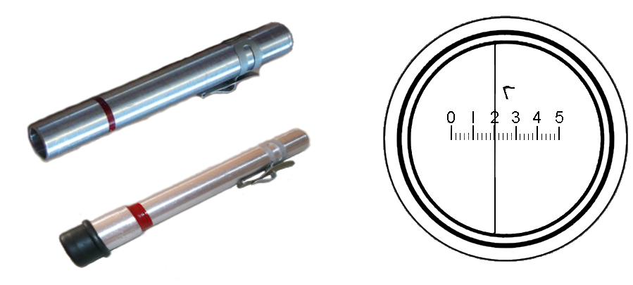
UK issued dosimeters had an aluminium barrel. Early issue devices did not have the bellows or retracting charging pin, instead they had a removable rubber cap with a clear window. Later versions had removable protective covers made out of soft plastic.
The quartz fibre dosimeter works by measuring the decrease in electrostatic charge on a metal conductor in an ionization chamber, due to ionization of the air in the chamber by radiation. It was invented in 1937 by Charles C. Lauritsen.
The dosimeter must be periodically recharged. It is usually read before it is charged, and the dose is logged, to chart one's exposure. Magnifying lenses, forming a low-power microscope, and an illumination lens allow one to directly read the dose at any time by aiming the illumination lens at a light source and looking into the device
The device is mainly sensitive to gamma and x-rays, but it also detects beta radiation above 1 MeV. It consists of a sealed air-filled cylinder called an ionization chamber. Inside it is a metal electrode strip that is attached to a terminal on the end of the pen for recharging. The other end of the electrode has a delicate gold-plated quartz fibre attached to it, which at rest lies parallel to the electrode. The ends of the chamber are transparent and the microscope is focused on the fibre.
Units with larger ranges had a capacitor attached between the electrode and the case. The capacitor stores a larger amount of charge on the device for a given voltage on the electrode. Since each radiation particle allows a fixed amount of charge to escape, a larger number of radiation particles is required to move the fibre a given amount.
During charging, the charger applies a high DC voltage, usually around 150-400 volts, to the electrode, giving it an electrostatic charge. The quartz fibre, having the same charge, is repelled by the surface of the electrode due to the coulomb force and bends away from the electrode. After charging, the charge remains on the electrode because it is insulated.
When a particle of ionizing radiation passes through the chamber, it collides with molecules of air, knocking electrons off them and creating positively and negatively charged atoms (ions) in the air. The ions of opposite charge are attracted to the electrode and neutralize some of the charge on it. The reduced charge on the electrode reduces the force on the fibre, causing it to move back toward the electrode. The position of the fibre can be read through the microscope. Within the device is a transparent scale marked with the required units, known as the graticule.
Since each radiation particle allows a certain amount of charge to leak off the electrode, the position of the fibre at any time represents the cumulative radiation that has passed through the chamber since the last recharge. Recharging restores the charge that was lost and returns the fibre to its original, zero, deflected position.
Various kinds of charger have been developed. In the UK, they were of two broad types. The first types issued used a hand generator similar to an old-fashioned telephone magneto. Later types used a single transistor inverter circuit powered by a D-type cell. Whilst the former types relied on a mirror reflecting ambient light up the dosimeter bore, later types included a small light bulb for illumination.
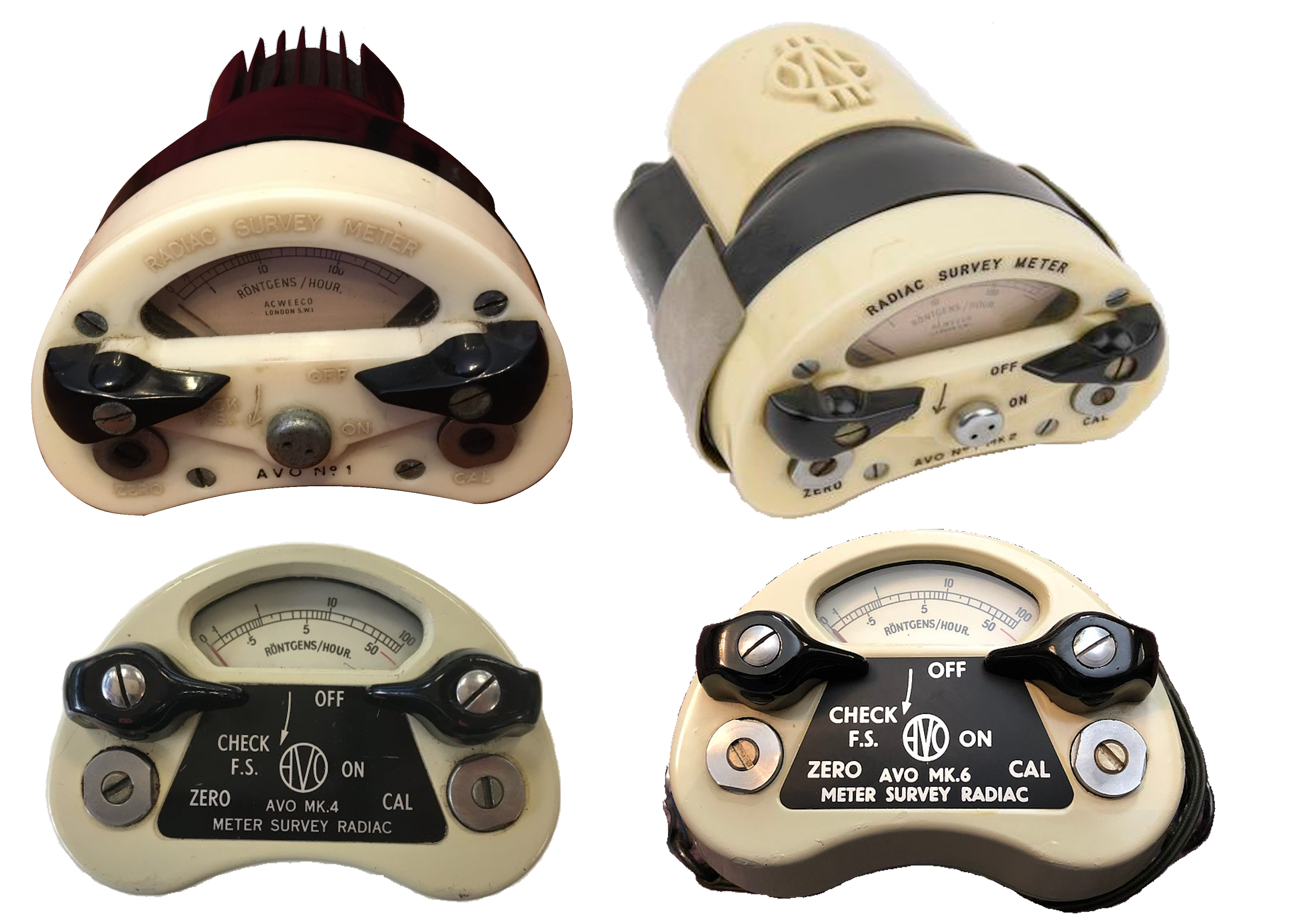
One training and three operational versions were issued to the Civil Defence Corps, WRVS and AFS with the following ranges:
- Training (No. 1) reading 0 - 0.5r.
- Operational (No. 2) reading 0 - 5r
- Operational (No. 3) reading 0 - 50r
- Operational (No. 4) reading 0 - 150r
- Type No. 1 measuring 0 - 0.5R. They were sometimes marked with a black identification band, and were often called the Training Type Individual Dosimeter.
- Type No. 2A measuring 0 - 5R. Identified by a blue band.
- Type No. 3 measuring 0 - 50R. Identified by a red band.
Personal dosimeter chargers
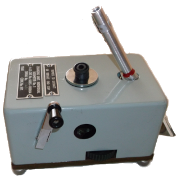
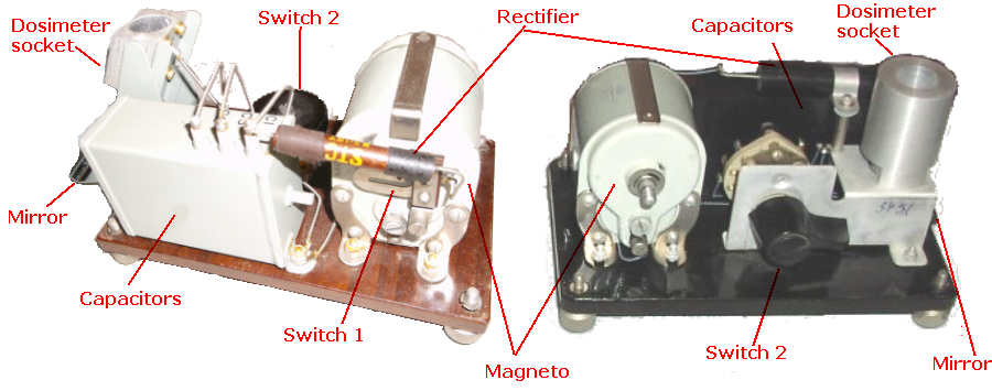
The first model of Dosimeter charger/reader issued to the civil defence services, and dates from about 1950. The Charger dosimeter No1 is operated by a hand generator, and reading is by way of ambient light reflected from a built-in mirror. The intention was for these to be placed at fixed points, e.g. sector warden posts, ROC posts and the like. The earliest issue had a device fitted to the top to enable the removal of the black protective cap from dosimeters, the later version omitted this. Winding the handle generated an AC voltage which was rectified by a selenium rectifier, which in turn charged a capacitor. A small amount of charge was then transferred from this capacitor to a 1nF capacitor by means of switch 2, and thence to the output capacitor. Switch 2 was operated by a thumbwheel.
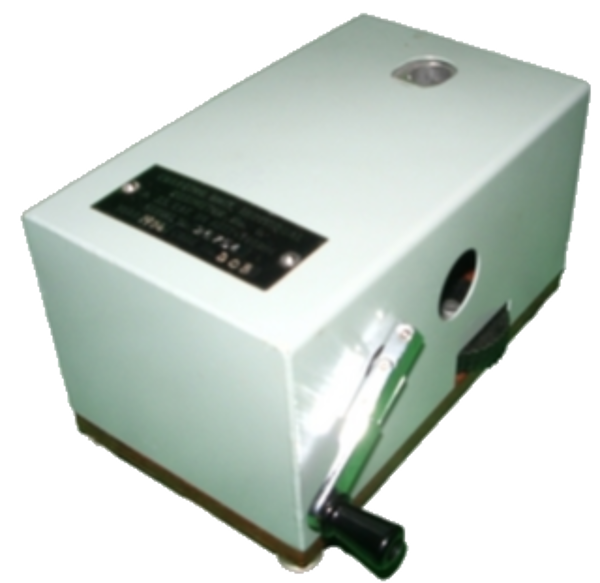
Charger, Dosimeter No 2 Mk 2
The No 2 Mk 2 model was similar in use to the No 1. Additions included a carrying strap and a socket cover. I never saw the purpose of the carrying strap. It was still available in the period 1964-8, as was the No 1. The actual circuit was pretty much identical to that of the No1 charger, but arranged differently in physical terms and with a two way charge/discharge switch. Again the first part of the instrument was a hand operated alternator, the output of which was used to charge a capacitor via a selenium rectifier. The charge was then switched via another pair of capacitors and a high value resistor to the charging socket. Light was still deflected up the dosimeter by way of a Mirror. The No 2 Mk 1 had a flat metal cover for the charging socket, this was an incomplete answer to contamination of the socket and interior of the device, it was replaced by a rubber stopper in the Mk 2. The No 1 and No 2 Mk 2 were succeeded by a battery operated device in about 1968. This latter was issued in small numbers to the Civil Defence Corps.Electronic dosimeter chargers
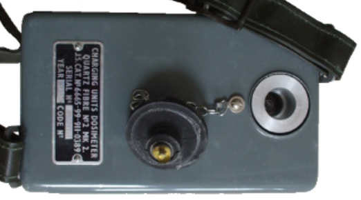
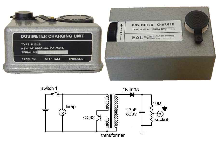
The Type N.105A was the most common used by the Royal Observer Corps. There is some evidence that another model by R. A. Stephen in Mitcham, Surrey, the P1548 was also issued, but I have been unable to confirm this. The P1548 circuit was identical to that of the N.105.A. The N.105.A used by the Royal Observer Corps, was introduced in 1967. It used a single germanium transistor circuit powered by a single U2 cell. In fact by the time it was introduced the transistor was already obsolete! Included was a small filament bulb to illuminate the scale of the dosimeter. Both of these battery operated devices had significant advantages over the earlier models. They were much lighter, less susceptible to internal contamination , did not need ambient light to read the dosimeters, and were easier to use when setting the fibre position. The only disadvantage was the need for a battery, but these were easy to obtain for local replacement. The Civil Defence Corps were due to have been issued a similar charger at the time of disbandment.
The switch is part of the charging socket, inserting the dosimeter turns the charger on, illuminating the scale, however the charging pin is not connected. This means the dosimeter can be read without re-zeroing it. Depressing the dosimeter further connects the pin, and it is then possible to zero it. Unlike the previous chargers the zeroing is continuously variable which makes it much easier to use. The user needs to be careful not to over depress the dosimeter otherwise there is a serious risk that the current reading may be changed or even cancelled.
Two other types of radiation measuring instruments were used in civil defence during the cold war, technically they were either ionisation chamber meters or Geiger counters. Ionisation meters and Geiger counters differ in their modes of operation, both of which are explained below.
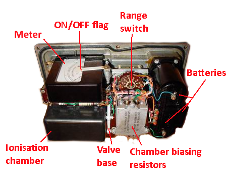
Ionisation chamber instruments
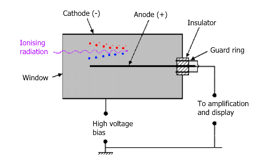
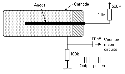
An ionisation chamber is a gas filled container, it detects radiation by measuring a voltage between two electrodes created by the flow of ions generated by radioactive particles, gamma or X-rays. Civil defence ionisation instrument chambers contain dry air at atmospheric pressure. Two electrodes, with a voltage (typically 15-100V), known as the polarising or bias voltage, across them form an electric field, and in the presence of ions in the chamber cause a flow of electric current between them. This flow is usually very small, in the femtoampere (one femtoampere is a billionth of a millionth (10-15) of an ampere) range, and detectable by electronic means.Survey meter simplified circuitThe chamber may be any shape with one electrode, the anode, consisting of either a simple rod or a flat plate. The wall of the chamber is usually metal and serves as the cathode connected to a negative potential. A large potential between the electrodes establishes an electric field between the two. The field is strong enough to pull the ion pairs, however not so strong that it creates further ions. In some cases the chamber has a thin wall made of some form of plastic.
When energetic radiation in the form of particles such as alpha, beta, or gamma rays interacts with the atoms of gas that that fill the chamber, they will either lose an electron or gain an electron. When an atom loses an electron, its overall charge becomes positive and therefore the cathode end of the chamber attracts it. However, when an atom gains an electron, its overall charge becomes negative and therefore the anode end of the chamber attracts it.
The flow of these ions therefore constitutes a flow of electron charge proportional to the amount of ions present. The flow of charge within the circuit is minute, this means an amplifier is utilised to make this tiny change more apparent.
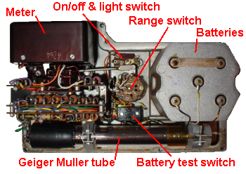
Both the Meter Doserate Portable No1 and the Meter Survey Radiac No 2 were built by E.K.Cole Ltd. of Southend-on-Sea, perhaps better known for the manufacture of radios and televisions under the brand name Ekco. E.K.Cole Ltd had been founded in 1924 by Eric Kirkham Cole and his girlfriend Muriel Bradshaw.
Meter Doserate Portable No 1
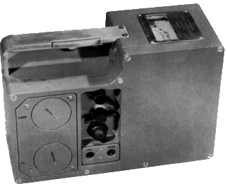
The Meter Doserate Portable No 1 had a single range of 0 - 3 r.p.h. This is an ionisation type meter and not a geiger counter. It was replaced with the No 2, because its single range was far too narrow for wartime use, consequently there are very few still in existence. This should not be confused with the Meter Doserate Portable No 1 Trainer, see above.The batteries comprised a pair of D cells and another obsolete HT battery. One D cell supplied the scale lamp, and the other the filament current for the electrometer valve. The D cells are contained behind the large circular covers, and CD personnel were permitted to change these. In the event of a spurious reading or a low battery test reading, the unit was meant to have been returned to the Servicing Department for testing and replacement of the HT batteries. These latter could be reached by removing the battery container, using the four screws around the D cell covers. In the front end, below the meter there was a humidity detector, which changed colour in the presence of moisture, if this happened the meter became inaccurate and again had to be returned.
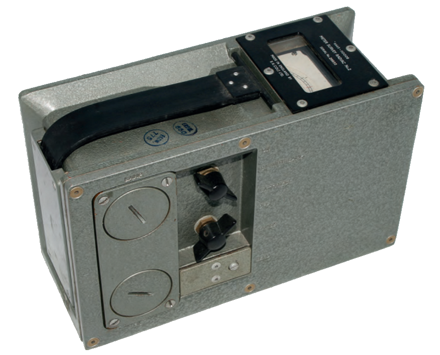
Meter, Survey, Radiac, No. 2
The Meter Survey Radiac No 2 is commonly sold on ebay and other sites as a geiger counter which it is not! These, again, are ionisation type meters intended for measuring fallout from nuclear attack. They will not measure, or even detect low-level radiation. If you get a reading on one, except in nuclear war conditions, or close in to a major nuclear incident (metres) then your meter is faulty!The dose-rate in Roentgen-hour (R/hr) is indicated on a direct reading meter with a linear scale. Three ranges are provided, 0-3R/hr, 0-30R/hr, 0-300R/hr. A moving scale on the meter is mechanically linked to the Range Switch to indicate the range in use . The ionisation chamber used has an air equivalent wall and the calibration is Independent of gamma energy, within 10%, over the energy range O.l - 1.0 MeV.
The instrument may be made sensitive to beta radiation by the removal of a panel which is normally screwed to the base of the instrument. A hinged flap and beta window assembly can be opened when the base panel is removed. When the beta flap is open, beta particles of energy greater than about 0.4MeV can penetrate to the ionisation chamber detector element.
The operational controls are situated on the side of the instrument. When used for gamma measurement the instrument may be carried in its haversack, access to the controls is then obtained through a flap on the side. The ON/ OFF switch operates a flag on the meter to indicate the position of this switch. The meter scale can be illuminated by a lamp for use when the instrument is operated in the dark. This instrument weighed about 6 lbs.
In addition to the two D cells required for the valve (tube) filament, and the meter lamp, this instrument required HT 9 volt and 30 volt batteries which were obsolete when the unit was introduced and had to be made to special order.
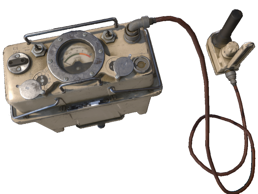
Meter Survey Lightweight (AVO RADIAC Meters)
This was the smallest and lightest ionisation Survey Meter issued to the civil defence services. As far as I am aware it was not issued to the Civil Defence Corps, although I did see one during training, recently acquired evidence shows that at least some county authorities had these meters in 1961. During training we were told that they were to be issued to the ROC only. The Survey Meter, Lightweight was built by the AVO company. The Mk 3 was first issued in about 1960 and had a logarithmic scale reading 0-100RPH. I can find no references to its use, but understand it was not popular due to reliability issues, the Meter Survey Radiac No 2 was much preferred, despite the fact that it weighed some three or four times as much. The first issue I can find reference is to the No 1 dating from the late 1950s. The last issue appears to have been of the Mk 6, which was the last issue prior to the PDRM 82 in 1982. Apparently these were only issued to ROC sector and group controls. The unit was provided with a neck strap but without any form of cover.
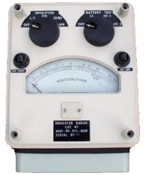
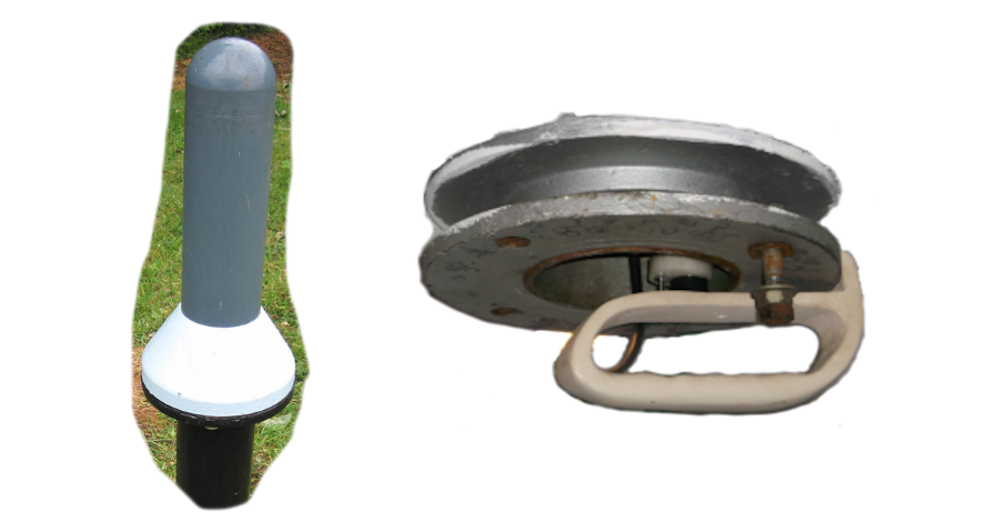
Fixed Survey Meter
The early model of the Fixed Survey Meter (FSM) was used by the Royal Observer Corps from the early 1950s until 1982/3, it was designed by the Atomic Weapons Establishment at Aldermaston and built by AVO, after that date the PDRM82F was used. The FSM was not used by other services. The PDRM82F was also referred to as the FSM in the training literature as it performed the same function. As the PDRM82F was a true geiger counter it is considered further below.Prior to the introduction of the FSM it was necessary for a post crew member to leave the relative safety of the underground post to take readings on the surface using a Meter Doserate Portable No1 or a Meter Survey Radiac No2. This was a hazardous operation in the event of fallout, and required de-contamination on re-entry to the post.
The FSM was battery operated, and had one fixed logarithmic scale from 0 to 500R/hr, which could be extended by the simple expedient of lowering the probe into a shielded position once it reached close to full-scale. It would read as low as 0.1R/hr at the bottom end of the scale.
The meter was connected by a co-axial cable to an ionisation chamber mounted onto a telescopic rod that was fed up a probe pipe in the ceiling of the monitoring post so that the probe was above ground. The top of the probe was protected by a polycarbonate dome that prevented fallout from entering the post.
The instruments were kept at the group controls in an air conditioned and de-humidified storage room and only issued to posts during Transition To War. Once at the posts the instrument was unpacked from its wooden transit case and prepared for use.
If radiation readings approached the 400R/hr level the telescopic rod was quickly collapsed and the probe reinserted to a distance below the surface that reduced the dial reading by a factor of ten. Thus the instrument became capable of producing accurate readings to a level of 5,000 roentgens per hour external reading. When reporting readings in the lower position this was signified to group control by prefixing the reading with word "RED". Once the level reached 400R/hr again, the probe was re-inserted to its full height.
Upon the first reading being received, this was reported to Group Control as "First Fallout", subsequent readings were reported as requested by Group. The FSM was replaced by the PDRM82(F) in 1982/3, this was a true geiger counter, and is described below.
The FSM was replaced by the PDRM82(F) in 1982/3, this was a true geiger counter, which is described below.
Setting up the FSM
This video is provided by the Imperial War Museum © IWM DRF 7121
under the terms of a non-commercial licence.
Geiger counters
A Geiger counter consists of a Geiger-Muller tube and associated electronics.Geiger tube operation
The Geiger-Muller tube consists of a sealed metallic or glass tube filled with argon or a mixture of noble gases mixed with a small amount of an organic gas or halogen gas. The noble gas is called the detecting gas whereas the halogen or organic are referred to as the quenching gas. The gas mixture inside the tube is at a pressure below atmospheric. A metal wire or rod runs through the centre of the tube, and is known as the anode. Either the metallic tube, a metallic cylinder or a conductive film lining the inner of the glass tube, in the case of a glass tube, forms the cathode. An electric potential of up typically 350-1500 volts is maintained between the anode and the cathode. In the absence of any radiation no current flows between the wire and the cylinder.When a radioactive particle, gamma or X-ray enters the tube it ionises an inert gas atom, releasing an electron. The resulting electron is accelerated towards the metal wire or anode.
As the electron approaches the metal wire it experiences an increasing electric field strength which in turn applies a greater accelerating force on the electron. The accelerating force becomes so strong that on collision with other argon atoms the electron can ionise them, releasing further electrons, generating a cascade of further electrons, an effect called the avalanche or Geiger effect. The ionisation by one particle can result in millions of electrons striking the metal wire. This only occurs within a limited range of applied voltages, known as the plateau region. In the centre of this range is the working voltage, for UK civil defence instruments this is in the range of 350-500 volts, on the larger tubes this value is typically marked on the tube itself. The avalanche produces a pulse for each original ionisation. Pulses are of equal amplitude, and the number of pulses indicates the number of events rather than the energy of the individual particles or gamma radiation.
The purpose of the quenching gas is to absorb the positive noble gas ions as they accelerate to the cathode. Without the quenching gas these positive ions will be neutralised at the cathode in an exited state or could even also dislodge electrons from the cathode. These dislodged electrons or excited atoms could trigger further ionisation creating a further voltage discharge giving inaccuracies in the measure from the device. When the quenching gas migrates to the cathode it recombines at ground state and so does not present the potential to cause any further ionisation. Some early UK tubes used an organic quenching gas, most later tubes contained bromine.
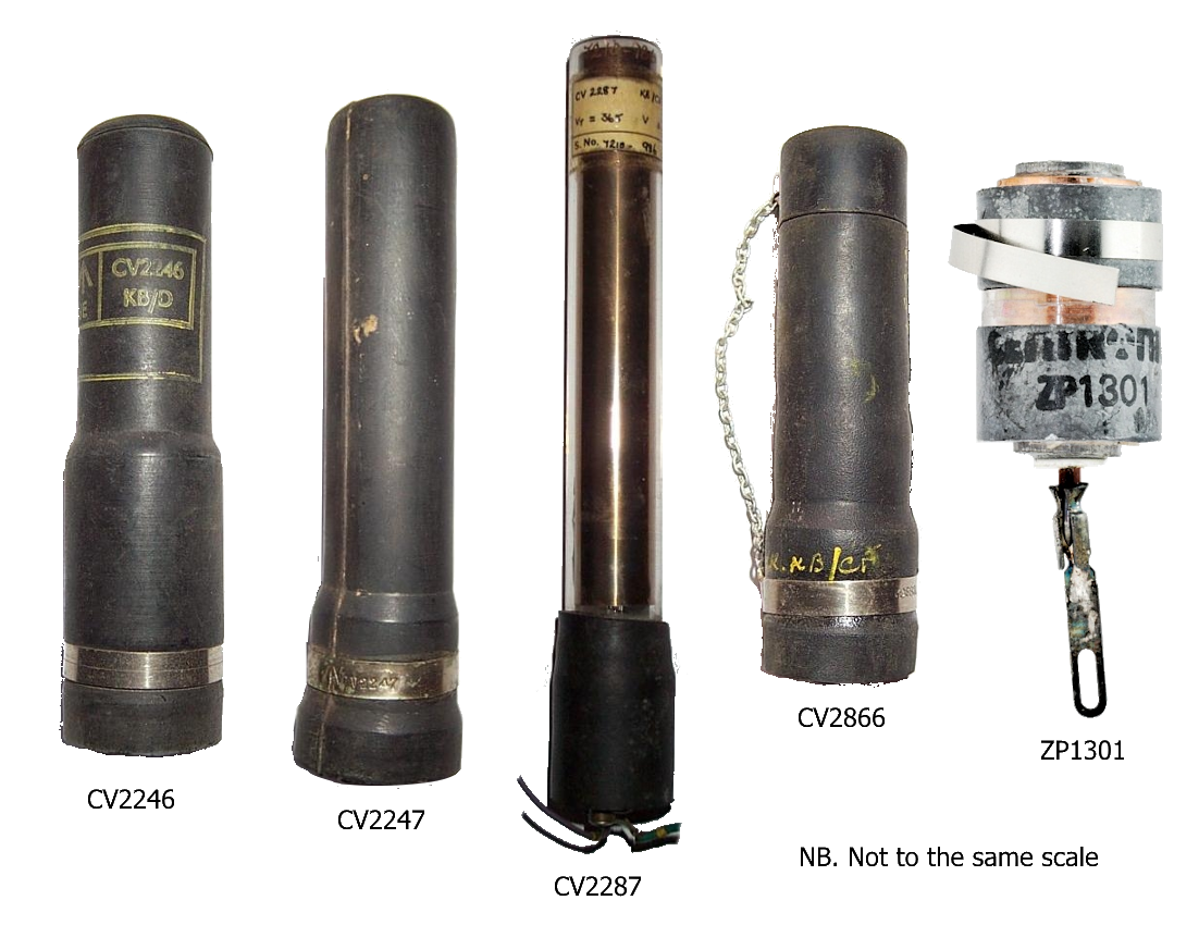
Special tubes were available for different purposes. For counting alpha radiation a special thin mica window is inserted in the end of a tube, no UK civil defence instruments were of this type. The CV2287 was used in the Meter Portable Training, it was sensitive to both high energy beta radiation and to gamma, but the metal case made the instrument only sensitive to gamma. The CV2246, CV2247, CV2248 were used in the Contamination Meter No 1 Mk1 and 2. The first two are sensitive to high energy beta particles and to gamma rays. The CV2248 has a glass well and was used for measuring radioactivity in liquids. The ZP1301 was fitted to the PDRM 82 and the PDRM 82F. It is a specially compensated tube that is only sensitive to gamma radiation above a certain energy. This latter tube, the ZP1301, also had an inbuilt radioactive check source. The initial issue only had a half life of just over ten years, later issues had a different isotope with a half life of 27 years. The later tubes can be identified by a small radiation trefoil label, some PDRM82s were also fitted with a later type tube from the same series.
Meter Doserate Portable No 1 Trainer
The purpose of the Meter Doserate Portable No 1 Trainer was to train personnel in the use of the Meter Doserate Portable No 1 (later also used for the No 2). Note the Geiger Muller tube at the bottom. This instrument used valve (tube) technology, with a D cell to provide the filament current, and HT batteries which were already obsolete by the time the instrument came into use and had to be made to special contract by Ever Ready. The geiger-muller tube is a CV2287 which is both large and sensitive. This tube is sensitive to hard beta radiation, the trainer itself is only sensitive to gamma radiation because of the thick-walled metal case. Although not intended for operational use it is a completely functional instrument, and could have been used as a contamination meter, although this purpose is not described in any of the civil defence literature or training manuals. It has a single range reading 0 - 300 microroentgens per hour. Meter illumination was by a small neon bulb. It was used by the military, Civil Defence Corps, Royal Observer Corps and the Auxiliary Fire Service.
Meter, Contamination No1
The Meter, Contamination No1 was issued in two variants, the No1 Mk1 and No1 Mk 2, the Mk1 had metal plugs for the probe, the Mk2 rubberised. It was a true Geiger counter that could be fitted with several different tube types. Contamination Meter No. 1Three different power supplies were available. The Battery Holder No1 was fitted with two 150 volt batteries. The Power Unit, Vibrator No1 used four 1.35 volt mercury cells. The Power Unit, Mains No 1, could operate from 100-120 volts or 200-250 volts ac, 50-60Hz. The latter unit is potentially lethal, as if it is plugged into the mains and not into the counter there are prongs exposed at mains potential.The controls were all on the top of the instrument, they comprised an on/off switch, headphone socket, meter, test switch, a connector for the probe, and two preset controls "A" and "B". Headphones were not issued to the civil defence services. The meter is roughly logarithmic and reads 0 to 10mR/hr. Preset control A is used to set the tube working voltage which needed to be done in a properly equipped workshop. Preset control B is used to set supply voltage if on test it reads outside of the correct range.
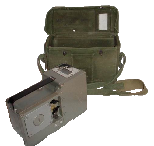
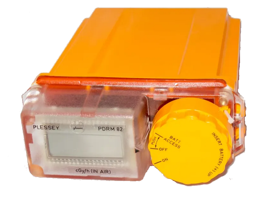
PDRM 82
The PDRM 82 was designed for
simplicity in operation, and was introduced to the ROC in 1982,
roll-out being completed by 1985. It was also issued to the fire
service and emergency planning officers. The PDRM 82 is a portable,
lightweight, water resistant gamma radiation survey meter to measure
radiological dose rate in the range 0.1 to 300 centiGrays per hour in
air. The Geiger Muller (G.M.) tube detecting unit is energy and polar
response corrected. This unit comes with a plastic neckstrap and a
waist lanyard. If, when switched on, the unit shows "FAIL", and
does not clear within 1 minute, then it is faulty. The most probably
cause of this is either the unit is damp internally, or the tiny
amount of radioactive isotope that forms part of the GM tube self test
is too weak, the half-life of the isotope used is 10 years, 27 years
or 30 years depending on which tube has been fitted, and the tube will
need replacing (expensive). No routine maintenance is required
or possible except for the replacement of the 3 'C' cells. It has a
large LCD display with a range of 0 - 300 cGy/h. The unit has a
battery life of about 400hrs.It is possible to modify the PDRM 82 to make it considerably more sensitive (about 1000x) by replacing the geiger tube at a cost of about £10-15, or to possibly re-activate a non-functioning unit. For details of the modification click here.
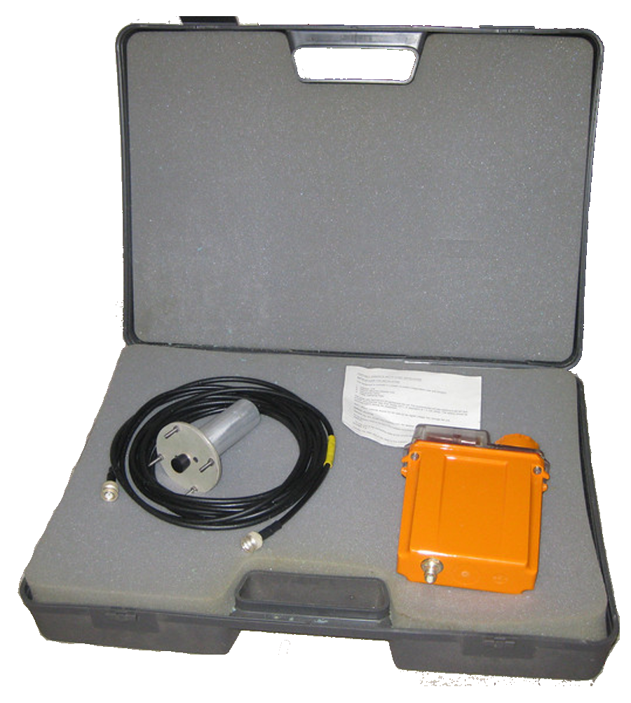
PDRM 82F
The PDRM82F is almost identical in appearance to the PDRM82, and shares virtually all of its circuitry.The most obvious differences are the bnc type socket on the rear and the external probe to which it connects via a coaxial cable. The PDRM82F replaced the earlier Fixed Survey Meter in the Royal Observer Corps starting in 1983, with roll-out completed by 1985. Its purpose was the same as that of the FSM, and in training materials the term FSM continued to be used. The external probe contained the same type of tube as the portable model. The display remained on the instrument table, and the probe was pushed up the ceiling mounted pipe in the monitoring room, and into the external plastic dome. To increase the range of reading, if the reading due to fallout approached 300cG/hr, then the probe would immediately be lowered to a more shielded position so that it gave 1/10 of the reading, and be clamped in that position.